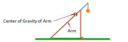
Inertia of Arm
Inertia of Arm is the moment of inertia of the entire arm around its center of gravity.
For an arm with a uniform cross-section along its length, the moment of inertia can be approximated by the formula,

where m is the mass of the arm, and L is the total length of the arm (Length of Long Arm + Length of Short Arm).
For a non-uniform arm, the moment of inertia can be found by breaking the arm up into simple shapes, finding the moment of inertia for each one, and then combining them together using the parallel axis theorem. A list of formulas for the moment of inertia of different shapes can be found here. See the Arm Example Calculations.
Alternatly, using a 3D CAD software package is probably the easiest way to find the inertia of a non-uniform arm.
For best performance, the moment of inertia of the arm should be as small as possible. This is why the arm is tapered on many trebuchets.
Note: When Auto Calculate is checked, the arm is assumed to have a uniform cross-section and the Inertia of Arm will be calculated automatically.